Light bends round small obstacles and spreads after a narrow opening. This bending and spreading is diffraction. Daily example: sound heard round a corner; light fringes at a razor edge. Interference is few waves; diffraction is many tiny waves adding up.
The one idea behind everything below: Fresnel half-period zones. Take a wavefront and cut it into rings so that each next ring is $\lambda/2$ farther from the screen point. Neighbour rings arrive out of phase and nearly cancel; the first zone dominates. Blocking alternate zones (zone plate) or adding many slits (grating) controls this sum.
Half-period zones — what they are and why equal areas matter
Step 1 — Construction. Take a plane wavefront and a screen point $P$ at distance $b$. Draw spheres centred at $P$ with radii $b$, $b+\lambda/2$, $b+\lambda$, … They cut the wavefront into rings — the half-period zones.
Step 2 — Areas nearly equal. The $n$-th zone boundary has radius $r_n$ with $r_n^2 = n\lambda b + n^2\lambda^2/4 \approx n\lambda b$ (drop $\lambda^2$ since $\lambda \ll b$). Zone area $= \pi r_n^2 - \pi r_{n-1}^2 = \pi\lambda b$ — independent of $n$. So every zone has nearly the same area $\pi b\lambda$.
Step 3 — Why it matters. Equal areas + alternate $\lambda/2$ path steps mean neighbouring zones send nearly equal amplitudes in opposite phase — they cancel pairwise, leaving only about half the first zone’s amplitude at $P$. This is the engine behind the zone plate (block alternate zones → no cancellation → bright focus) and behind straight-edge fringes.
Fresnel vs Fraunhofer diffraction (exam table)
| Point | Fresnel | Fraunhofer |
|---|---|---|
| Source/screen | at FINITE distance | at INFINITY (lenses used) |
| Wavefront | spherical / cylindrical | plane |
| Zones | half-period zones counted | single-slit strips / grating slits |
| Examples | straight edge, slit, wire, zone plate | single/double/multiple slit, grating |
| Math | zone areas, Cornu spiral | $\sin\theta$ path differences |
Fraunhofer single slit — minima and intensity
Step 1 — Setup. Slit of width $a$, plane wave in, lens brings parallel rays to the screen. Consider direction $\theta$.
Step 2 — Divide into strips. Split the slit into narrow strips. The path difference between the top and bottom edges is $a\sin\theta$. Pair strips $\lambda/2$ apart in path: they cancel.
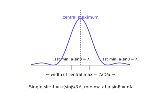
Step 3 — Minima. Full cancellation when $a\sin\theta = n\lambda$ ($n = \pm1, \pm2, \ldots$): the slit divides into $2n$ half-wave strips that kill each other pairwise.
Step 4 — Intensity. Adding all strips with their phases gives amplitude $A = A_0(\sin\alpha/\alpha)$ with $\alpha = (\pi a\sin\theta)/\lambda$, so
Central maximum at $\alpha = 0$ ($I = I_0$); zeros exactly at the minima $a\sin\theta = n\lambda$; secondary maxima (much weaker, $\approx I_0/22$, $I_0/61$, …) sit between. Width of central maximum $= 2\lambda/a$ in $\sin\theta$ — narrower slit, wider spread.
Fraunhofer double slit — interference × diffraction
Two slits of width $a$, centres $d$ apart. Each slit diffracts (envelope $(\sin\alpha/\alpha)^2$); the two centres interfere ($\cos^2\beta$ fringes with $\beta = (\pi d\sin\theta)/\lambda$):
Equally spaced interference fringes ($\beta = n\pi$: $d\sin\theta = n\lambda$) sit INSIDE the single-slit diffraction envelope — the envelope kills fringes where it has zeros (missing orders when $d/a$ is an integer ratio).
Multiple slits → grating (bridge)
With $N$ slits the $\cos^2\beta$ sharpens into principal maxima of width $\sim 1/N$: $I = I_0(\sin\alpha/\alpha)^2(\sin N\beta/\sin\beta)^2$. Large $N$ gives the razor-sharp grating orders of Formula 2 — the grating is just the many-slit limit of the double slit.
Fresnel patterns — straight edge, slit, wire
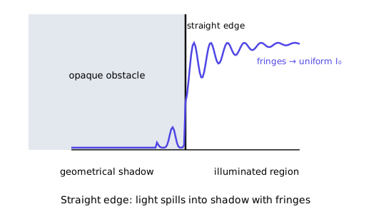
No lenses: count half-period zones directly. Straight edge: above the geometric shadow edge, zones are progressively uncovered → fringes of decreasing contrast fading into uniform light; inside the shadow, zones are progressively covered → smooth fall to zero (no fringes). Narrow slit: symmetric fringes on both sides of the bright centre. Thin wire: bright centre INSIDE the geometric shadow (zones from both sides agree there) flanked by fringes — the Poisson/Arago-style surprise for an obstacle.
Resolving power
Rayleigh criterion. Two point images are just resolved when the central maximum of one falls on the first minimum of the other.
Grating resolving power. In order $n$ with $N$ total lines illuminated, $R = \lambda/\Delta\lambda = nN$ — more lines and higher order resolve closer wavelengths. (Proof sketch: the $n$-th principal maximum has half-width $\Delta\theta$ with $N(a+b)\cos\theta,\Delta\theta = \lambda$; two wavelengths are resolved when their angular separation $n,\Delta\lambda/[(a+b)\cos\theta]$ equals this.)
Telescope/microscope (statement). Circular aperture: $R = D/1.22\lambda$ (telescope); microscope: $d_{min} = 1.22\lambda/2\mu\sin\alpha$. Learn the grating one by proof, these by statement.
Here $r_n$ = radius of the $n$-th zone boundary. $b$ = plate-to-screen (image) distance for a plane wave from infinity. $f$ = first (primary) focal length. $r_1$ = first zone radius. $(a+b)$ = grating element (one slit width $a$ + one opaque gap $b$ = grating period). $N = 1/(a+b)$ = lines per unit length. $\theta_n$ = angle of the $n$-th principal maximum. $n = 0, \pm1, \pm2\ldots$ = order.
Zone plate — construction, foci, vs convex lens
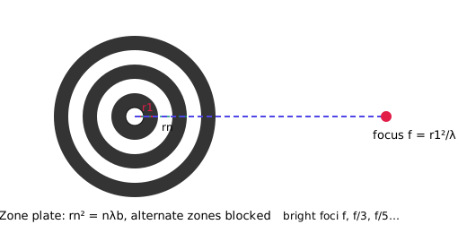
Construction (exam steps). (i) Compute $r_n = \sqrt{n\lambda b}$ for chosen $\lambda$ and $b$. (ii) Draw concentric circles of radii $r_n$ on paper. (iii) Blacken alternate rings (all odd or all even). (iv) Photograph it reduced to get a fine plate.
Why it focuses. Open zones differ by $2\times\lambda/2 = \lambda$ in path, so they all arrive in phase at $f$ — bright spot. Other points give extra foci at $f/3$, $f/5$, … (odd fractions) where the phase still lines up.
Zone plate vs convex lens (memorise the table):
| Point | Zone plate | Convex lens |
|---|---|---|
| Works by | diffraction (blocking zones) | refraction (glass bending) |
| Foci | many: $f$, $f/3$, $f/5$, … | one (nearly) |
| Colour | highly chromatic ($f \propto 1/\lambda$) | nearly achromatic |
| Brightness | dimmer (half the light blocked) | bright (all light through) |
| Image | diffracted orders + background | single clean image |
Trap: longer wavelength gives SHORTER focal length ($f = r_1^2/\lambda$), so red focuses nearer than violet, opposite of a glass lens.
Plane grating — element and spectrometer method
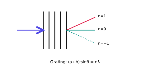
Spectrometer method (exam steps). (i) Collimator gives a parallel beam on the grating at normal incidence. (ii) Turn the telescope to order $n$ on the left, read angle; repeat on the right; half the difference = $\theta_n$. (iii) With known $(a+b) = 1/N$, compute $\lambda = (a+b)\sin\theta_n/n$. Use several orders and average.
Highest order: $|\sin\theta_n| \le 1$ gives $n_{max} < (a+b)/\lambda$ — take the integer below the ratio.
Solved PYQs
What is a zone plate? Explain its construction. Compare it with a convex lens.
2019202220232024×4Recall
Steps
- Definition: a plate of concentric rings, alternate zones transparent/opaque, which focuses light by diffraction.
- Zone radii: the "next ring $\lambda/2$ farther" condition gives $r_n^2 = n\lambda b + n^2\lambda^2/4 \approx n\lambda b$ since $\lambda \ll b$.
- Construction: compute, draw, blacken alternate, photo-reduce (4 steps above).
- Focus: open zones agree in phase → bright image at $f = r_1^2/\lambda$, plus $f/3$, $f/5$, … (odd fractions).
- Table: diffraction vs refraction, many foci vs one, chromatic vs achromatic, dimmer vs brighter (5 rows).
Answer
Exam tip
What is a plane diffraction grating? Define grating element (grating constant). Describe the method of determining the wavelength of monochromatic light using a grating and a spectrometer.
2019202220232024×4Recall
Steps
- Define grating: many parallel equal slits, $N$ lines/cm, so the grating element is $(a+b) = 1/N$.
- Quote the grating equation $(a+b)\sin\theta_n = n\lambda$ — neighbouring slits differ by $(a+b)\sin\theta_n$, in-phase when $= n\lambda$.
- Spectrometer: collimator → normal incidence on grating; telescope reads $\theta_n$ on the left and on the right; $\theta_n$ = half the difference.
- Compute $\lambda = (a+b)\sin\theta_n/n$ for orders $n = 1, 2$ and average; higher $n$ spreads more, so precision is better.
- Validity: normal incidence, monochromatic source, grating plane vertical.
Answer
Exam tip
Find the highest order of the spectrum with sodium light, given (i) $\lambda = 5.89\times 10^{-5}$ cm and $3000$ lines/cm (2022); (ii) $\lambda = 5896$ Å and $2000$ lines/cm (2023).
20222023×2Recall
Steps (2022)
- Element: $(a+b) = 1/3000$ cm $= 3.333 \times 10^{-4}$ cm.
- Ratio: $(a+b)/\lambda = 3.333 \times 10^{-4}/5.89 \times 10^{-5} = 33.33/5.89 = 5.658$.
- Integer below: $n_{max} = 5$ — order $6$ would need $\sin\theta > 1$.
Steps (2023)
- Convert: $\lambda = 5896$ Å $= 5896 \times 10^{-8}$ cm $= 5.896 \times 10^{-5}$ cm; element $(a+b) = 1/2000 = 5.0 \times 10^{-4}$ cm.
- Ratio: $5.0 \times 10^{-4}/5.896 \times 10^{-5} = 50.0/5.896 = 8.480$.
- Integer below: $n_{max} = 8$ — 9th order cannot emerge.
Answer
Exam tip
In a plane transmission grating the wavelength of light is $500$ nm and the second-order principal maximum is obtained at $30^\circ$. Find the number of lines per cm on the grating.
2019Recall
Steps
- Given: $\lambda = 500$ nm, $n = 2$, $\theta_2 = 30^\circ$, $\sin 30^\circ = 0.5$.
- Element: $(a+b) = n\lambda/\sin\theta = 2 \times 500/0.5 = 2000$ nm.
- Convert: $2000$ nm $= 2000 \times 10^{-7}$ cm $= 2.0 \times 10^{-4}$ cm.
- Lines: $N = 1/(2.0 \times 10^{-4}) = 5000$ per cm.
- Sense: $5000$/cm is a standard coarse grating — fine gratings run $\sim 15000$/cm.
Answer
Exam tip
What are half-period zones of a wavefront?
202220232024×3Recall
Steps
- Setup: a wavefront (plane or spherical) and an observation point $P$ at distance $b$.
- Construction: with centre $P$, draw spheres of radii $b$, $b+\lambda/2$, $b+2\lambda/2$, …; where they cut the wavefront gives the zone boundaries.
- Meaning of "half-period": waves from successive zones reach $P$ with $\lambda/2$ extra path = half a period out of phase.
- Zone radius: $r_n^2 \approx n\lambda b$ (drop the $\lambda^2$ term since $\lambda \ll b$).
- Key property: every zone has nearly equal area $\pi b\lambda$ — proved in Q6.
- Use: neighbouring zones nearly cancel at $P$; only about half the first zone survives — the basis of the zone plate.
Answer
Exam tip
Show that the areas of the half-period zones of a plane wavefront are nearly equal.
20192024×2Recall
Steps
- Geometry: $n$-th zone boundary satisfies $r_n^2 + b^2 = (b+n\lambda/2)^2 = b^2 + nb\lambda + n^2\lambda^2/4$.
- So $r_n^2 = n\lambda b + n^2\lambda^2/4$ — exact.
- Area of $n$-th zone: $A_n = \pi r_n^2 - \pi r_{n-1}^2 = \pi\lambda b + \pi(2n-1)\lambda^2/4$.
- Since $\lambda \ll b$ (light: $\lambda \sim 10^{-7}$ m vs $b \sim 1$ m), the $\lambda^2$ term is $\sim 10^{-7}$ times the first — drop it.
- Hence $A_n \approx \pi b\lambda$, independent of $n$ — all zones nearly equal. ∎
Answer
Exam tip
Distinguish between Fresnel diffraction and Fraunhofer diffraction.
20192024×2Recall
Steps
- Distances: Fresnel — source and screen at finite distances; Fraunhofer — both effectively at infinity (lenses bring them there).
- Wavefront: Fresnel uses spherical/cylindrical wavefronts; Fraunhofer uses plane wavefronts.
- Method: Fresnel counts half-period zones; Fraunhofer adds $\sin\theta$ path differences across strips/slits.
- Examples: Fresnel — straight edge, narrow slit, wire, zone plate; Fraunhofer — single/double/multiple slits, grating.
- Write the table — five rows, each one mark.
Answer
Exam tip
Find the intensity distribution of Fraunhofer diffraction pattern due to a single slit.
2019202220232024×4Recall
Steps
- Slit width $a$, plane wave in; in direction $\theta$ the edge-to-edge path difference is $a\sin\theta$.
- Split the slit into many narrow strips; strip at position $x$ contributes amplitude $\propto e^{i(2\pi x\sin\theta/\lambda)}dx$.
- Integrate $x$ from $-a/2$ to $a/2$: resultant amplitude $A = A_0\cdot\sin\alpha/\alpha$ with $\alpha = \pi a\sin\theta/\lambda$.
- Intensity: $I(\theta) = I_0(\sin\alpha/\alpha)^2$ — boxed as Formula 1b.
- Read off: central maximum $I_0$ at $\theta = 0$; zeros at $\alpha = n\pi$, i.e. $a\sin\theta = n\lambda$ (Formula 1a); weak secondary maxima between.
- Sketch: tall central lobe of width $2\lambda/a$, side lobes $\approx 1/22$, $1/61$ of $I_0$ — the Fig above.
Answer
Exam tip
In Fraunhofer diffraction due to single slit, the slit of width $0.3$ mm is illuminated by light of wavelength $5890$ Å. Calculate the angular position of the 2nd minima.
20192024×2Recall
Steps
- Given: $a = 0.3$ mm $= 3.0\times 10^{-4}$ m; $\lambda = 5890$ Å $= 5.89\times 10^{-7}$ m; $n = 2$.
- Formula: $\sin\theta_2 = 2\lambda/a$.
- Substitute: $\sin\theta_2 = 2\times 5.89\times 10^{-7}/(3.0\times 10^{-4}) = 1.178\times 10^{-6}/3.0\times 10^{-4}$.
- Arithmetic: $1.178/3.0 = 0.3927$; $10^{-6}/10^{-4} = 10^{-2}$; so $\sin\theta_2 = 3.927\times 10^{-3}$.
- Small angle: $\theta_2 \approx 3.927\times 10^{-3}$ rad $= 0.225°$.
Answer
Exam tip
Derive an expression for the intensity distribution for Fraunhofer diffraction due to double slit.
2019Recall
Steps
- Two slits of width $a$, centres $d$ apart; plane wave in, direction $\theta$.
- Each slit alone gives amplitude $\propto (\sin\alpha/\alpha)$ with $\alpha = \pi a\sin\theta/\lambda$ (from Q8).
- The two slit-centres differ in path by $d\sin\theta$, i.e. phase $2\beta$ with $\beta = \pi d\sin\theta/\lambda$; adding two equal phasors gives $2\cos\beta$.
- Multiply: total amplitude $A \propto (\sin\alpha/\alpha)\cdot 2\cos\beta$.
- Square: $I(\theta) = 4I_0(\sin\alpha/\alpha)^2\cos^2\beta$ — Formula 1c.
- Read off: $\cos^2\beta$ gives equally spaced interference fringes ($d\sin\theta = n\lambda$); the $(\sin\alpha/\alpha)^2$ envelope suppresses fringes near its zeros (missing orders).
Answer
Exam tip
Distinguish between resolving power and magnifying power.
20192024×2Recall
Steps
- Define magnifying power: how much bigger the image looks — ratio of angular sizes (telescope/microscope). It only enlarges.
- Define resolving power: the ability to show two CLOSE objects as separate — limited by diffraction, not by lenses.
- Key contrast: magnifying without resolving gives a big blur — "empty magnification". A high-$M$ eyepiece on a poor objective shows nothing new.
- Formulas: grating $R = \lambda/\Delta\lambda = nN$; telescope $D/1.22\lambda$ — resolving power grows with aperture/lines, magnifying power with focal lengths.
- One-line summary: magnification enlarges, resolution reveals.
Answer
Exam tip
Reference. Brij Lal, Subrahmanyam & Avadhanulu — Optics Ch-16 (Fresnel zones, zone plate), Ch-17 (grating, spectrometer, resolving power), Ch-18 (Fraunhofer slits); Ajoy Ghatak — Optics Ch-15, 16.